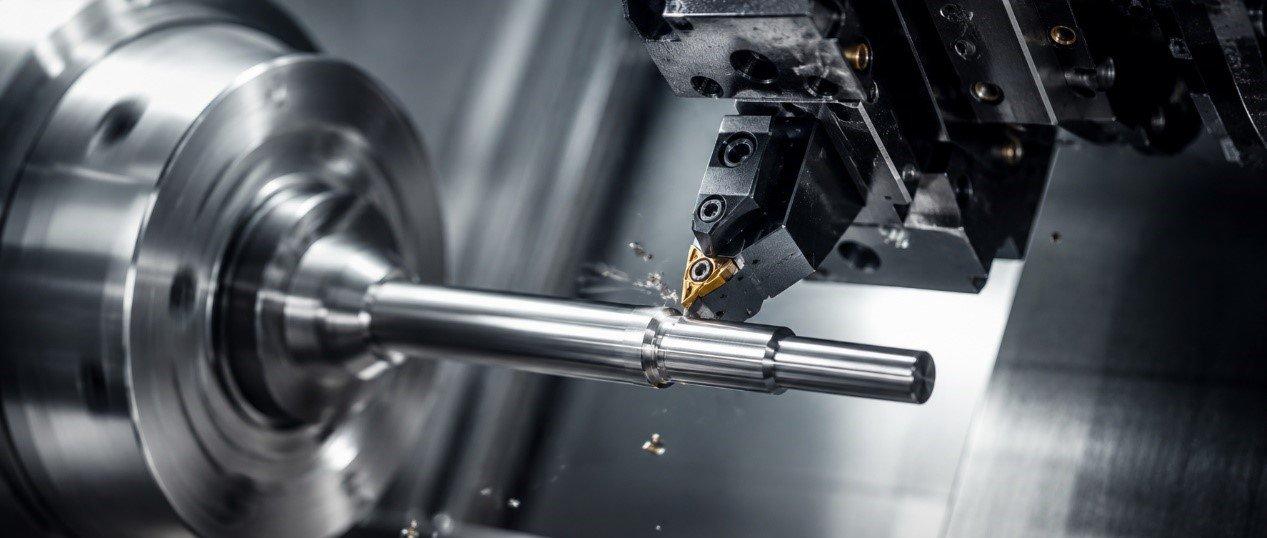
In CNC turning, machining slender shafts—typically defined as workpieces with a length-to-diameter ratio (L/D) greater than 10—is widely recognized as one of the most challenging operations. Due to their low rigidity, slender workpieces are highly susceptible to chatter, resulting in repetitive chatter marks, inconsistent diameters that resemble a "bamboo" pattern, and even tool insert chipping.
This article explores practical solutions for stable slender shaft machining, from proper steady rest setup to optimizing cutting force distribution based on machining physics.
Why Are Slender Shafts So Prone to Chatter?
Understanding the underlying machining physics is the first step toward solving the problem. Most machining failures involving slender shafts can be traced to two primary factors.
1. Excessive Radial Cutting Force
When a cutting tool engages the workpiece, cutting forces are generated in three directions. Among them, the radial cutting force acts perpendicular to the workpiece axis and pushes the slender shaft away from the cutting tool.
Because the workpiece lacks sufficient rigidity, it deflects under load and then springs back. This repeated deflection creates a self-excited vibration known as regenerative chatter, one of the primary causes of poor surface finish and unstable machining.
2. Centrifugal Force and Thermal Expansion
At high spindle speeds, centrifugal force can cause bowing effect of long, slender workpieces. Meanwhile, heat generated during machining causes thermal expansion.
Since the workpiece is constrained between the chuck and the tailstock center, thermal growth cannot occur freely along the axial direction. Instead, the shaft bends laterally, further increasing vibration and reducing dimensional accuracy.
Practical Steady Rest Applications
A steady rest serves as the third support point for slender shaft machining. However, one critical preparation step is often overlooked before installing the steady rest—machining the support journal.
1. Proper Installation Procedure
Turn a Steady Rest Spot
Never position the steady rest fingers directly on a rough or out-of-round bar surface. Instead, lightly turn a short section at the intended support location to create a steady rest spot.
This ensures the support surface is round and concentric with the spindle axis.
Adjust the Steady Rest Rollers
Move the steady rest to the machined support journal and adjust the steady rest rollers until they make light, even contact with the workpiece.
Proper lubrication—or roller-type support fingers—is recommended to minimize friction and prevent thermal deformation during machining.
Verify Alignment with a Dial Indicator
For best results, mount a dial indicator on the turret and rotate the spindle while checking the support journal.
This helps verify that the steady rest is supporting the workpiece without pushing it away from the true centerline.
2. Reverse Feed Turning
Reverse feed is one of the most effective methods for suppressing chatter during slender shaft turning.
Principle
Instead of feeding from the tailstock toward the spindle, program the cutting tool to move from the spindle toward the tailstock (positive Z-axis direction).
Benefits
This changes the axial cutting load from compression to tension.
Just as a stretched string becomes stiffer, a slender shaft under tensile loading exhibits significantly higher rigidity. The increased stability greatly reduces chatter and improves surface finish.
Optimizing Cutting Conditions and Tool Geometry
With Fanuc-controlled CNC lathes, machining stability can often be improved by adjusting cutting parameters to direct cutting forces in a more favorable direction.
1. Selecting the Right Tool Geometry
Entering Angle
An entering angle between 90° and 95° is recommended.
A larger entering angle reduces radial cutting force while directing more of the cutting force along the workpiece axis toward the spindle or tailstock. This minimizes workpiece deflection and improves machining stability.
Nose Radius
Use a smaller nose radius whenever possible, such as R0.2 mm or R0.4 mm.
A larger nose radius increases the contact area between the insert and the workpiece, which generates higher radial cutting forces and increases the likelihood of chatter.
2. Recommended Cutting Parameters
Example: Medium Carbon Steel (S45C)
| Machining Stage |
Cutting Speed Vc (m/min) |
Feed Rate (mm/rev) | Depth of Cut ap (mm) | Programming Recommendations |
| Rough Turning |
100–150 |
0.20–0.30 | 1.5–2.5 | Use the G71 rough turning cycle together with a reverse-feed machining strategy. |
| Finish Turning | 150–200 | 0.05–0.12 | 0.2–0.5 | Enable Spindle Speed Variation (SSV) to suppress chatter during finishing. |
The Advantages of Focus CNC Lathes
The Focus CNC FBL-360/460 and FBL-500 Series were designed with large shaft machining in mind.
Both the headstock and tailstock are engineered for excellent thermal stability, while the machine bed has been optimized using Finite Element Analysis (FEA) to effectively absorb high-frequency vibration during heavy-duty machining.
For extra-long and slender workpieces, Focus CNC also offers a programmable hydraulic steady rest interface that integrates seamlessly with Fanuc controls. This enables automated multi-position support, improving both machining stability and production efficiency.
Conclusion
Successful slender shaft machining is not simply about applying more cutting power—it is about controlling the physics of the machining process.
By machining an accurate support journal, properly setting up the steady rest, and using reverse feed to convert compressive forces into tensile loading, manufacturers can significantly reduce chatter and achieve superior dimensional accuracy and surface finish.
Combined with the rigidity and thermal stability of Focus CNC lathes, these machining practices help deliver reliable, high-quality production for even the most demanding slender shaft applications.