When you are turning thin-wall parts on a CNC lathe — aerospace sleeves, medical device housings, anything with a wall under 3 mm — clamping distortion is the problem that causes the most headaches. The part often ends up "triangulated" from the three jaw marks, or the bore goes out of round, and the part fails final inspection after finish turning.
Should you switch from a standard hydraulic chuck to a pneumatic chuck for thin-wall work? To make the right decision, you first have to understand how these two systems generate clamping force differently, and the cutting physics hiding behind that clamping action.
Power Source and Pressure Control: What the Numbers Really Mean
Do not compare hydraulic pressure and pneumatic pressure by their gauge readings alone. The actual clamping force the jaws apply to the part is determined by system pressure x cylinder piston area x chuck mechanical advantage, not by the pressure number by itself.
| Criteria |
Hydraulic rotary cylinder system |
Pneumatic front-mount / rear-mount cylinder system |
| Working pressure range |
3 to 35 kgf/cm2 |
2 to 8 kgf/cm2 |
| Maximum clamping force | Very high (suited to heavy cutting) | Medium to low (suited to light cutting and secondary operations) |
| Low-pressure control limit | Below 3 to 5 kgf/cm2, thrust can become unstable due to internal seal friction | Naturally suited to low pressure — stays stable even down to 2 kgf/cm2 |
| Pressure source stability | Very good (hydraulic oil is nearly incompressible, supplied by a dedicated hydraulic unit on the machine) | Weaker (air is compressible, and pressure can drop if other equipment in the shop is drawing from the same air line) |
| Suitability for thin-wall parts | Needs significant setup experience and special fixtures | The first choice for thin-wall parts — gentle clamping force is less likely to cause permanent distortion |
Practical Recommendations
If you are evaluating a thin-wall machining setup, here is how to think it through.
- Pure thin-wall production (medical tubing, aluminum optical rings, and similar parts): Go with a pneumatic chuck. Paired with a pressure regulator and an air dryer, a pneumatic system gives you soft clamping that a hydraulic system simply cannot match, and that is what protects your yield.
- A general-purpose machine that handles both heavy cutting and thin-wall finishing. Stick with a standard hydraulic chuck, but use full-contact soft jaws to cover the part completely. Before your final finish pass, build an "unclamp and re-clamp lightly" step into your program to release the distortion stress built up during roughing. Pair this with a two-stage pressure function, and use an M-code to switch to low pressure for the finish cut.
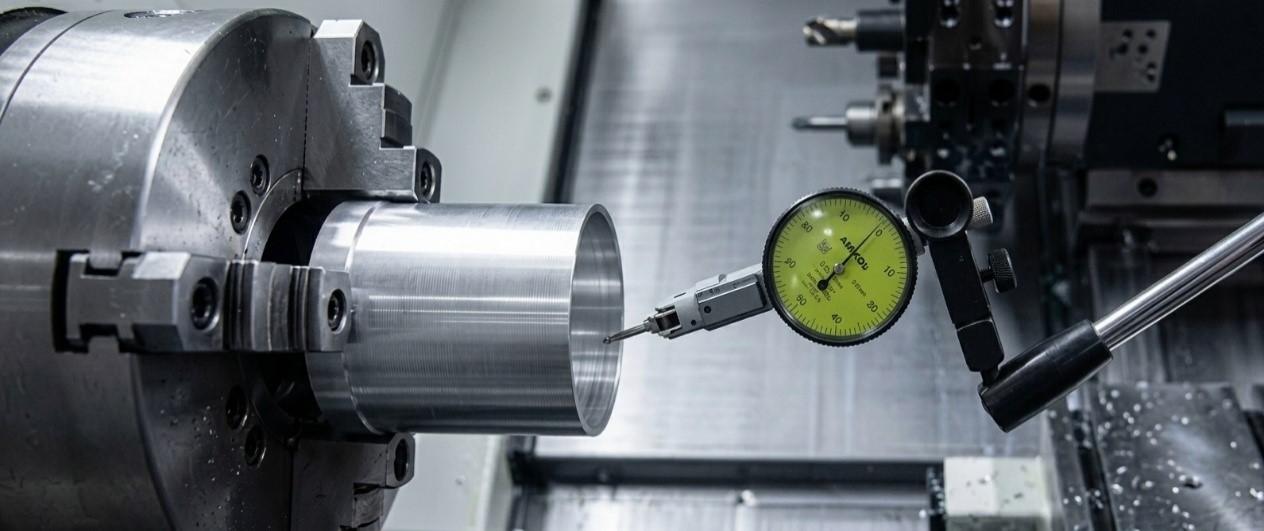
- Using a dial indicator to check your setup. Do not rely on feel alone when you are dialing in thin-wall clamping pressure. After clamping, always check the part's outer or inner diameter with a dial indicator. If the needle moves more than one-third of your tolerance the moment you clamp, that tells you the clamping force is already causing elastic distortion you cannot see with the naked eye.
Building a Stable Setup for Thin-wall Machining
There is no single chuck system that fits every thin-wall machining application. Pneumatic chucks can be useful when low and gentle clamping force is the priority, while hydraulic chucks provide greater flexibility when the same machine also needs to handle heavier cutting. The right choice depends on the workpiece material, wall thickness, required tolerance, cutting load, and production process.
When planning a CNC lathe setup for thin-wall parts, the chuck should therefore be considered together with jaw design, pressure control, spindle configuration, and machining strategy. Focus CNC offers CNC lathe solutions for different machining requirements. If you are evaluating a machine or clamping configuration for a specific workpiece, contact Focus CNC to discuss your part specifications and production requirements.