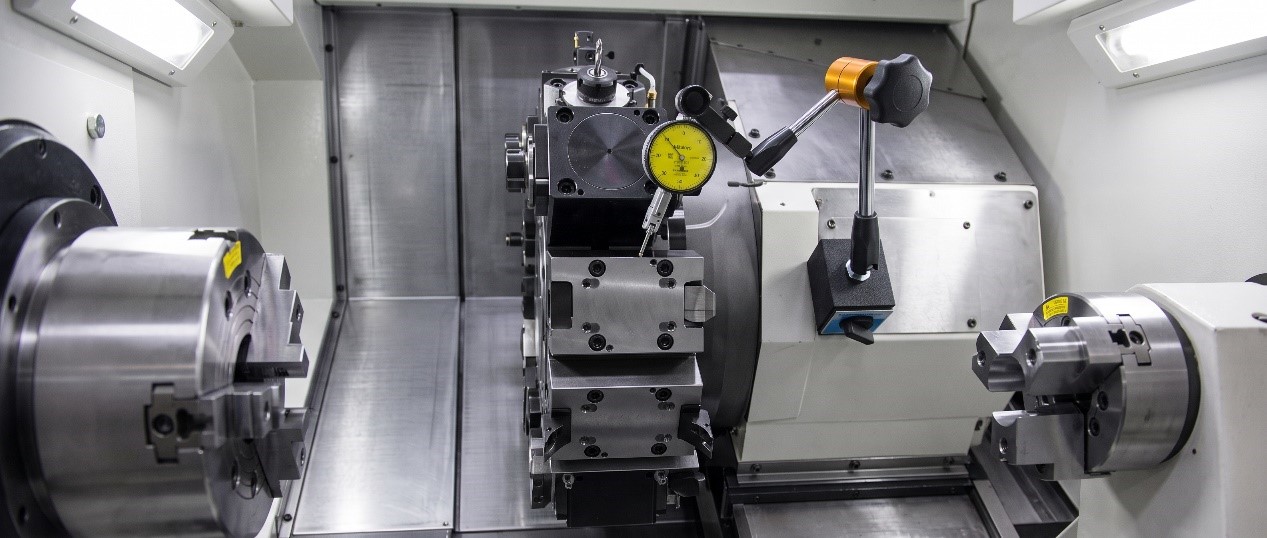
When a CNC lathe experiences a severe crash — such as the turret hitting the chuck, spindle, or workpiece at high speed — the visible damage is often only part of the problem. The most easily overlooked but serious issue is the machine’s geometric accuracy.
A strong impact can slightly shift the spindle, deform the guideways, move the turret out of alignment, or even twist the machine bed. These changes are hard to see with the naked eye, but they directly cause unstable dimensions, poor surface finish, abnormal tool wear, and repeated center pips or taper problems.
In these situations, simply resetting parameters or correcting tool offsets is not enough. In real-world maintenance, experienced service technicians will first inspect the machine’s geometry with precision measuring tools to determine whether adjustment or part replacement is necessary.
Below are the 4 most critical geometry items you must check and recalibrate after a severe crash.
1. Parallelism Between the Spindle Centerline and Z-Axis Travel
This is one of the most important geometric references on a CNC lathe. After a crash, the spindle may tilt slightly. If the spindle rotation axis is no longer parallel to the Z-axis travel direction, the machine will cut a taper instead of a true cylinder.
Inspection and Adjustment Method
- Mount a 150 mm bar in the chuck and perform an OD turning cut on the bar. Then use a micrometer to measure the diameter difference between both ends.
- Install two dial indicators so the probes contact both ends of the bar and zero them out.
- Loosen the spindle adjustment bolts and monitor the indicator readings while adjusting the spindle alignment according to the diameter difference measured by the micrometer.
- After adjustment, perform another OD turning cut and measure both ends again. Repeat the process until there is no measurable diameter difference.
If Not Corrected The diameters at both ends of the workpiece will not match, and long shaft machining will always have taper error.
2. Parallelism Between the Turret and Z-Axis Travel
A crash can twist or shift the turret body on the saddle. When this happens, the tool path is no longer parallel to the spindle centerline.
Inspection and Adjustment Method
- Select a reference tool station on the turret and install a boring bar holder with a 150 mm test bar.
- Mount a dial indicator on the spindle face or chuck face. Set the probe against the side of the test bar and zero the indicator.
- Move the Z-axis through its full travel and observe the reading change along the bar.
- If deviation is found, record the values and adjust the turret using the turret adjustment screws.
Recommended Tolerance If possible, adjust the deviation to within 0.005 mm. At minimum, it should be controlled within 0.01 mm.
If Not Corrected During drilling or deep boring operations, the hole axis may become badly misaligned, causing tapered bores or even drill breakage. This seriously affects part assembly accuracy.
3. Parallelism Between the Turret and X-Axis Travel
A crash may also shift the turret disk or cause the tool holders to become misaligned with the X-axis. This changes the cutting angle of the tool.
Inspection and Adjustment Method
- Use a dial indicator with the probe contacting the turret disk surface. Move the X-axis and observe the reading difference across the turret surface at a single tool station.
- If deviation is found, remove the turret front cover and loosen the turret disk mounting bolts. Use a soft mallet to gently tap and adjust the turret disk position.
Recommended Tolerance If possible, adjust the deviation to within 0.005 mm. At minimum, it should be controlled within 0.01 mm.
If Not Corrected During radial turning, the tool path will no longer stay square to the spindle centerline. This can cause poor face flatness or geometric errors when machining shoulders and chamfers.
4. Concentricity Between the Spindle Center and Tool Holder Center
This is one of the most common problems after a crash. When the turret is pushed in the X-axis direction by impact force, the tool holder centerline no longer matches the spindle rotation center.
Inspection and Adjustment Method
- Install a coaxial indicator in the chuck and position the probe inside the boring bar holder bore. Rotate the coaxial indicator one full turn and observe the reading variation.
- Move the X-axis until the reading variation becomes zero.
- Reset the relative position on the controller screen and move the X-axis in the X+ direction by a specified distance. Set this position as the new X-axis machine zero point. (For example, on Fanuc controls this can be set using parameter 1815 bit 4.)
If Not Corrected Part dimensions may become inconsistent after every tool change. When facing to center, a small center pip will always remain on the workpiece. Uneven cutting force will also shorten insert life significantly.
Conclusion: Early Recalibration Prevents Hidden Losses
After a spindle or turret crash, a CNC lathe may still appear to run normally even when important geometry errors remain. However, without properly correcting these 4 key geometry items, the machine can become a money pit, continuing to produce unstable or defective parts.
Taiwan-made CNC lathes are generally well known for strong machine rigidity and reliable after-sales support, making repairs faster and easier. But accurate and careful geometry inspection is still the absolute key to bringing the machine fully back to proper working condition.
Want to learn more about CNC lathe technology? Subscribe to our blog. In the next article, we’ll discuss machining parameters and machine rigidity requirements for the difficult-to-cut nickel-based alloy Inconel 718.